Smart Plug Custom Firmware
Reversing and flashing a BK7321N based Smart Plug with ESPHome. Soldering, UART communication and firmware extraction involved.
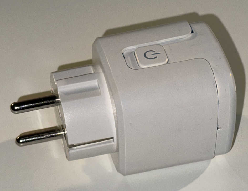
On the market there are some smart plugs, in the sense that they can be remotely switched on and off and that they can measure power consumption, that can be bought for cheap. So I decided to get one from AliExpress (link) for 5.5€ (shipping included). It has a female Schuko (CEE 7/3) socket and a CEE 7/7 male connector that fits in either French or Schuko sockets. These kind of plugs get shipped with a close-source firmware preinstalled that allows the user to remotely control them with an app (SmartLife most of the time), which requires the plug to be connected to the internet. Since I want full control over it and I don't want a IoT device that "phones home" on my LAN, I decided to 'jailbreak' it and flash a custom firmware. Since ESPHome recently added support for the LibreTiny platform (enabling it to run on the microcontroller present in the plug) and I already have other devices flashed with it, I went for it. An alternative firmware, which I also tried, is OpenBK7231 (or OpenBeken).
Preparation
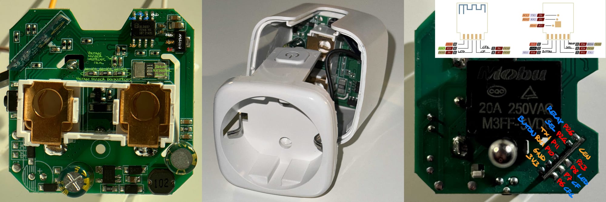
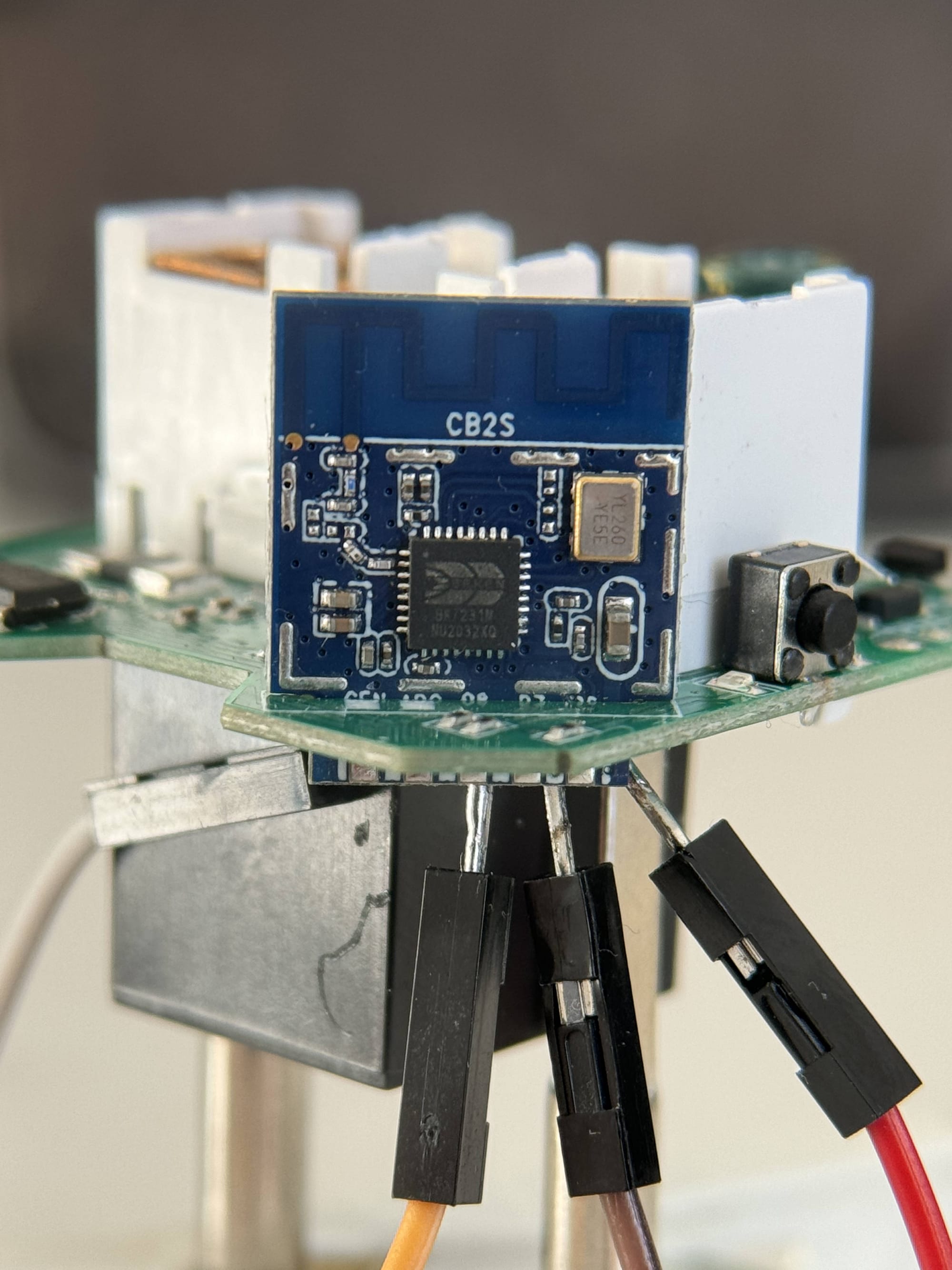
To clarify the terminology used in this post: the chip is the blue PCB, labelled CB2S, which contain the microcontroller, the antenna and some passive components; the MCU is the microcontroller, which in my case is a BK7231N; the board is the green PCB on which all components are soldered; the plug is the whole package; the firmware is the compiled code that's flashed on the MCU.
 tuya-cloudcutter
 Some older version of the stock firmware can be exploited by wireless vulnerability that allows to flash custom firmware over-the-air (OTA). For those devices it's possible to jailbreak them without physical access to the chip pins. To check the stock firmware version, install the SmartLife app (select 'Try as guest' to skip account creation) and connect the plug to it: start the pairing in the app, plug the device into power and hold power button until it starts flashing rapidly (around 15 seconds, flashes at 2 Hz). In the app's 'Device Information' section, copy the MAC address and check it on macaddress.io ensuring that the company name is Tuya Smart Inc. In the 'Device Update' section, look for the Main Module version and check here to see if it is a known patched version. In my case it was 1.1.15, which is patched, so to install a custom firmware serial flashing is needed. To access the chip pins, the plug needs to be taken apart.
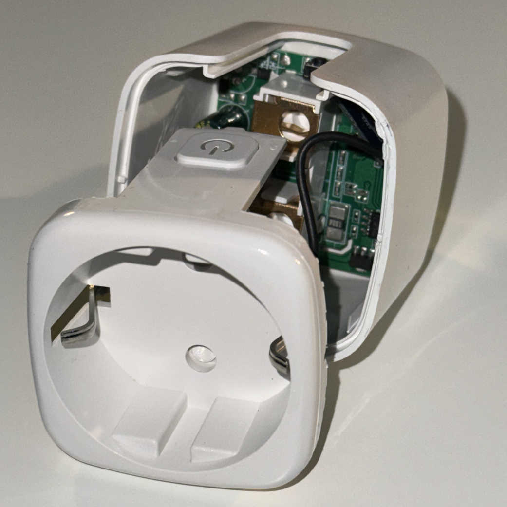
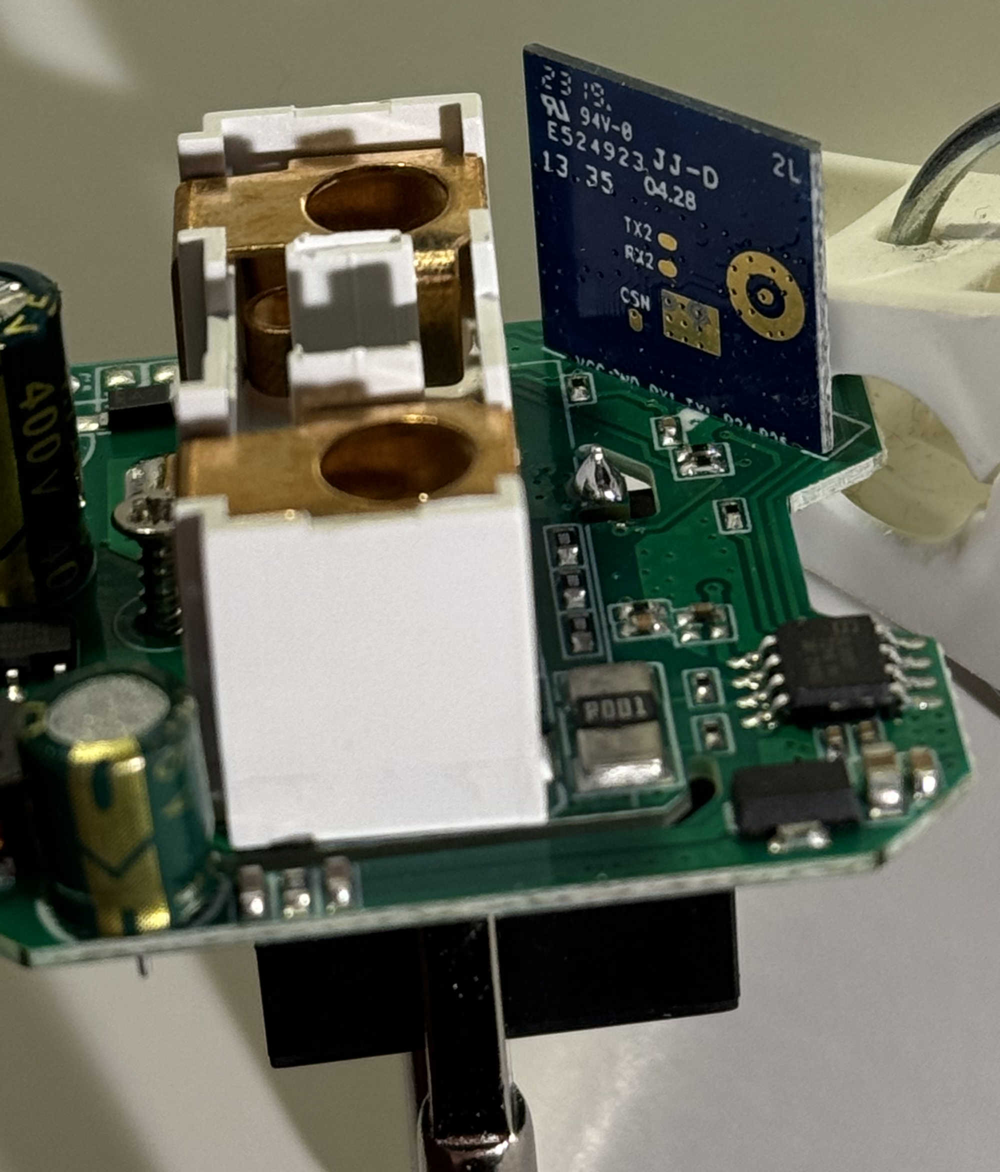
With the plug disassembled and the board exposed, identify the exact MCU and chip name. In my case the MCU is a BK7231N and the chip name is CB2S. The chip name is needed later when configuring the firmware. To communicate with the MCU via UART, solder wires to the RX1 and TX1 pins as well as the GND pin. Depending on how you want to power the chip, solder a wire on the 3V3 pin of the chip or the 5 V input of the voltage regulator (photo of the top part of the board appears later). There are several ways to power the chip, ranging from best to less preferable:
- UART adapter 5 V output ⭤
AMS11175 V input pin - UART adapter 3V3 output ⭤ Chip 3V3 pin
- Plug connected to mains power (be careful)
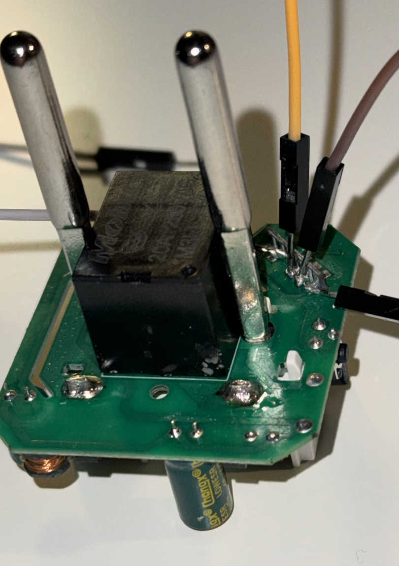
I initially powered the chip via the 3V3 pin, but in this way the relay does not work since it operate on a 5 V signal. Instead of messing with the board voltage regulator AMS1117, I carefully connected the disassembled plug to mains power.
Connect the UART to USB adapter to the soldered pins, ensuring that the TX and RX pins are swapped (UART TX ↔ RX chip, UART RX ↔ TX chip), and make sure to have a shared ground between the chip and the UART adapter. Now, the PC can read and write the chip's flash memory content. Install bk7231tools with pipx install bk7231tools[cli].
tuya-cloudcutterFor the operation of bk7231tools, the chip need to be put in download mode, which is entered while the chip communicates with the flasher program. While the program is trying to establish communication, the chip has to be reset (rebooted). To do that, you need to temporary bridge CEN pin to GND with a wire shortly after (~ 3 seconds) starting the program. Alternatively, you can briefly cut the power to the chip, however using the CEN pin is recommended. Upon a successful connection, bk7231tools will continue its operations.
We are now ready to tinker with our smart plug, but before moving further it's best to make a backup of the stock firmware loaded on the chip's flash memory.
Backing up the flash
To backup (dump) the content of the chip flash memory use the bk7231tools program previously installed. The following command should hang up before printing the Connected! message. Reset the chip and it should continue.
$ bk7231tools read_flash -d /dev/ttyUSB0 dump_stock_full_2mb.bin
Connected! Chip info: 0x7231c / Flash ID: eb 60 15 / Protocol: FULL
Reading 2097152 bytes from 0x0
Reading 4k page at 0x200000 (0.00%)
⋮
Reading 4k page at 0x3FF000 (99.80%)
To be on the safe side, dumping again and ensuring that the two file's checksum match is suggested. To dissect and extract the dumped file:
$ bk7231tools dissect_dump -e -O dump_stock_full_2mb/ dump_stock_full_2mb.bin
RBL containers:
        0x10f9a: bootloader - [encoding_algorithm=NONE, size=0xea20]
        0x129f0a: app - [encoding_algorithm=NONE, size=0xefd60]
Storage partition:
        0x1ee000: 60 KiB - 12 keys
        - 'gw_bi'
        - 'user_param_key'
        - 'gw_di'
        - 'tls_ca_cnt'
        - 'timer_arr'
        - 'gw_wsm'
        - 'wf_start_md'
        - 'is_stride'
        - 'gw_ai'
        - '000004p5i3'
        - 'ble_beaconkey'
        - 'em_sys_env'
Firmware preparation and Reverse Engineering
Board schematic, mains power to 5 V conversion not shown:
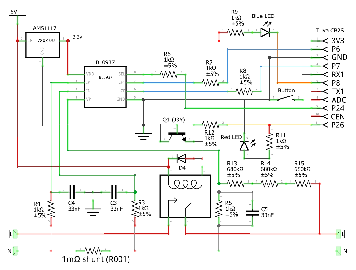
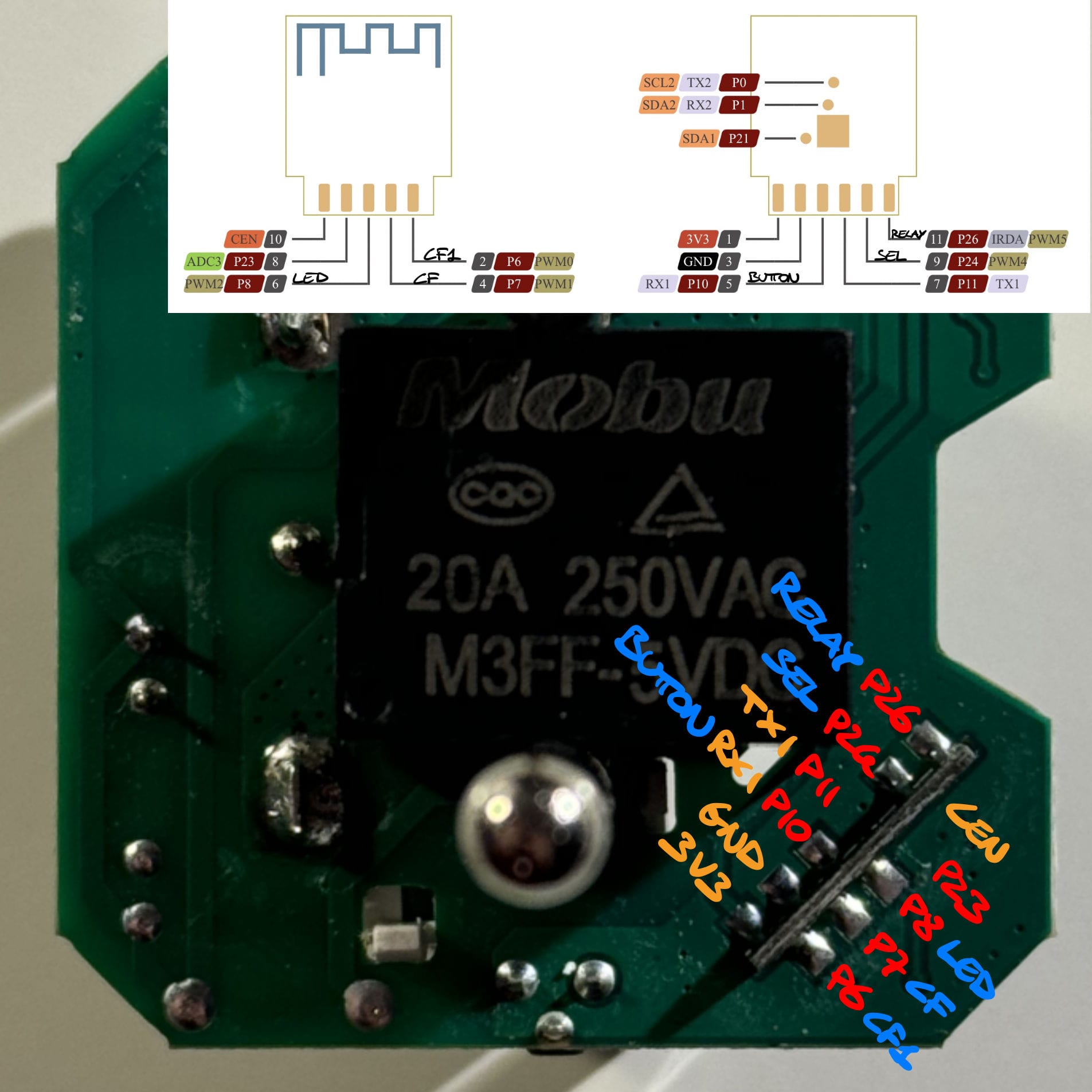
Note that my upstream resistances (R13, R14, R15) in the voltage divider are 660 kΩ, and the downstream resistance is R5. The button's pin RX1 is P10 and note that the AMS1117 pins are not drawn in the same order as the physical component. For accurate pin mapping, refer to the datasheet or consult the annotated board photo. The power monitoring chip is BL0937 (datasheet, ESPHome component).

As specified in the ESPHome component description, the value of several resistors are needed to correctly measure the power consumption. Measure (or read from the resistor code if not possible) the values of sensing resistances indicated in the board photo.
- Current Shunt Resistor: R001 = 1 mΩ
- Voltage Divider Upstream: 80D = 660 kΩ
- Voltage Divider Downstream: 1 kΩ
For the R001 resistance I could not accurately measure it while for the 80D one I measured any one of the three to be 660 kΩ and 1980 kΩ if measuring the three in series. The voltage_divider option for the power sensor BL0937 must be calculated as (3*v_div_upstream + v_div_downstream)/v_div_downstream, which in my case is 1981. This value, along with the resistance of the shunt resistor, are needed in the sensor configuration.
Here is the configuration file that I used, to compile it run esphome compile smartplug.yml:
esphome:
  name: smartplug-1

bk72xx:
  board: cb2s

substitutions:
  device_name: 'SmartPlug 1'

logger:
  hardware_uart: UART1

api:
  encryption:
    key: "HOME_ASSISTANT_API_ENC_KEY"

ota:
  password: ""

wifi:
  ssid: "WIFI_SSID"
  password: "WIFI_PSW"
  fast_connect: on
  manual_ip:
    static_ip: 192.168.123.123
    gateway: 192.168.1.1
    subnet: 255.255.0.0
    dns1: 192.168.1.1
    dns2: 1.1.1.1
  ap:
    ssid: "${device_name} Fallback Hotspot"
    password: "FALLBACK_WIFI_PSW"
    ap_timeout: 1min

captive_portal:

web_server:
  port: 80

button:
  - platform: restart
    id: restart_button
    name: 'Restart ${device_name}'
    entity_category: diagnostic

status_led:
  pin:
    number: P8
    inverted: true

switch:
  - platform: gpio
    id: relay
    pin: P26
    name: '${device_name}'
    restore_mode: RESTORE_DEFAULT_OFF
    icon: mdi:power-socket-de

binary_sensor:
  - platform: gpio
    id: switch_button
    pin:
      number: P10
      inverted: true
    on_release:
      then:
        - switch.toggle: relay
    internal: true

sensor:
  - platform: hlw8012
    model: BL0937
    current_resistor: 0.001
    voltage_divider: 1981  # (660×1000×3 + 1000)/1000
    sel_pin:
      number: P24
      inverted: true
    cf_pin: P7
    cf1_pin: P6
    current:
      name: '${device_name} Current'
    voltage:
      name: '${device_name} Voltage'
    power:
      name: '${device_name} Power'
    energy:
      name: '${device_name} Energy'
      # convert to kWh
      # filters:
        # - multiply: 0.001
      # unit_of_measurement: 'kWh'
      # accuracy_decimals: 4
    update_interval: 60s
    change_mode_every: 3
Flashing OpenBK7231 via UART
Before installing ESPHome I wanted to try OpenBK7231. Download the firmware binary from the GitHub release section, select the correct platform (MCU) and the UART Flash version. In my case the file is OpenBK7231N_QIO_1.17.334.bin.
openshwprojectsTo flash the chip, connect to it as done before and run the bk7231tools write_flash command shown below. When it hangs up before printing the Connected! message, reset the chip. Upon a successful connection, bk7231tools will begin to flash the new firmware.
$ bk7231tools write_flash -d /dev/ttyUSB0 -s 0 -S 0 --bootloader OpenBK7231N_QIO_1.17.334.bin
Connected! Chip info: 0x7231c / Flash ID: eb 60 15 / Protocol: FULL
Writing 1220464 bytes to 0x0
Trying to unprotect flash memory...
Erasing and writing at 0x200000 (0.00%)
⋮
Erasing and writing at 0x329000 (99.68%)
Verifying CRC
The current command timeout of 1.0 second(s) is too low for reading 1220608 bytes CRC. Increasing to 4 second(s).
OK!
After resetting the chip, a WiFi access point named OpenBK7231N_ABCDEF01 (where ABCDEF01 are the last 8 hex value of the chip's MAC address) will appear; connect to it. Opening http://192.168.4.1/index will lead to the welcome page. Click the button Launch Web Application (link) and in the Config top tab, on the Devices section it's possible to load an existing configuration. In my case a compatible preset is Tuya Elivco EU Smart Socket 16A (BK version) (source). Click on the Copy Device Settings and then on the Save Pins buttons to load that preset. Now the welcome page should display the relay status and the power measurements. To connect the smart plug to a WiFi network and modify additional options open the Config page (link). Once everything is correctly configured dump the firmware as a backup and remember to reset the chip to exit download mode.
Flashing ESPHome
Initially, trying to flash ESPHome via UART resulted in two failed attempts. Using esphome run command resulted in ValueError: No response received after resetting the chip (the explanation present on the LibreTiny documentation is wrong since I have no problem of flashing the chip without changing the power supply and the reset timing is irrelevant) while trying to flash the generated firmware file directly with bk7231tools write_flash -d /dev/ttyUSB0 -s 0 -S 0 --bootloader .esphome/build/smartplug-1/.pioenvs/smartplug-1/esphome_2023.11.6_cb2s_bk7231n_lt1.4.1.uf2 resulted in the error Input data is larger than flash memory size.
I then discovered that the app partition (image_bk7231t_app.0x011000.rbl), which is for some reason significantly smaller than the full firmware image (esphome_2023.11.6_cb2s_bk7231n_lt1.4.1.uf2), can be flashed independently from the bootloader. If restoring the bootloader is needed, use bk7231tools write_flash -d /dev/ttyUSB0 -s 0 -S 0 -l 0x11000 --bootloader dump_stock_full_2mb.bin. If the original firmware dump is not available (bad, I told you to do a backup before messing up) use the one from the OpenBK7231 firmware, just replace the file in the previous command. The LibreTiny documentation explains the nature of the .rbl file: "image_bk7231t_app.0x011000.rbl App partition - flashable at 0x11000", so flash this app partition with the start parameter -s 0x11000:
$ bk7231tools write_flash -d /dev/ttyUSB0 -s 0x11000 -S 0 .esphome/build/smartplug-1/.pioenvs/smartplug-1/image_bk7231n_app.0x011000.rbl
Connected! Chip info: 0x7231c / Flash ID: eb 60 15 / Protocol: FULL
Writing 1150832 bytes to 0x11000
Trying to unprotect flash memory...
Erasing and writing at 0x211000 (0.00%)
⋮
Erasing and writing at 0x329000 (99.66%)
Verifying CRC
The current command timeout of 1.0 second(s) is too low for reading 1150976 bytes CRC. Increasing to 3 second(s).
OK!
As an alternative, since I previously flashed OpenBK7231, it's possible to flash ESPHome via an OTA update in two ways. I'm now assuming that the chip's WiFi is in AP mode, exposing the web interface on 192.168.4.1 and the PC is connected to that AP with local IP 192.168.4.100. The first OTA updating method is via http://192.168.4.1/ota: on the PC connected to the same LAN as the plug, start an http server (listening on the correct address) to serve the firmware files previously obtained after running esphome compile smartplug.yml:
$ ip a | grep wlp3s0
3: wlp3s0: <BROADCAST,MULTICAST,UP,LOWER_UP> mtu 1500 qdisc noqueue state UP group default qlen 1000
    inet 192.168.4.100/24 brd 192.168.4.255 scope global dynamic noprefixroute wlp3s0

$ cd .esphome/build/smartplug-1/.pioenvs/smartplug-1
$ rclone serve webdav . --addr 192.168.4.100:8080
Ensure that the web server is up and running by visiting http://192.168.4.100:8080/, the content of the folder .esphome/build/smartplug-1/.pioenvs/smartplug-1 should be visible. In particular, we need the link to the OTA file image_bk7231n_app.ota.rbl (http://192.168.4.100:8080/image_bk7231n_app.ota.rbl). In the OpenBK7231 OTA page, paste this link when requested for the OTA file and confirm the update.
The second method for updating OTA is via the web application: on the welcome page, click the button Launch Web Application (link) and in the top bar select the OTA tab. Uploading the previous file image_bk7231n_app.ota.rbl results in the error Invalid OTA file was selected (probably it's expecting a new OpenBK7231 version), so for the moment the only method to flash ESPHome OTA seems to be the first one.
To check if the plug correctly runs the freshly flashed firmware and joins the WiFi specified in the .yml configuration file, ping it's IP address previously defined in the smartplug.yml config file: ping -a 192.168.123.123. The plug should join the WiFi network with it's web interface exposed on port :80 (if defined in the .yml config file) and can be added in HomeAssistant. Once ESPHome has been flashed, and if the ota components is present in the .yml config file, it's possible to run esphome run smartplug.yml and flash the firmware via OTA.
Power Sensor Debugging
Unfortunately, when using ESPHome, the power monitoring function seems broken for my specific configuration. Logging with level: VERY_VERBOSE set in the .yml config file shows the following errors:
⋮
[23:17:19][D][hlw8012:082]: Got power=0.0W, voltage=0.0V
[23:17:19][V][sensor:043]: 'SmartPlug 1 Voltage': Received new state 0.000000
[23:17:19][D][sensor:093]: 'SmartPlug 1 Voltage': Sending state 0.00000 V with 1 decimals of accuracy
[23:17:19][V][json:038]: Attempting to allocate 512 bytes for JSON serialization
[23:17:19][V][json:058]: Size after shrink 84 bytes
[23:17:19][VV][api.service:140]: send_sensor_state_response: SensorStateResponse {
  key: 2498278327
  state: 0
  missing_state: NO
}
[23:17:19][V][sensor:043]: 'SmartPlug 1 Power': Received new state 0.000000
[23:17:19][D][sensor:093]: 'SmartPlug 1 Power': Sending state 0.00000 W with 1 decimals of accuracy
[23:17:19][V][json:038]: Attempting to allocate 512 bytes for JSON serialization
[23:17:19][V][json:058]: Size after shrink 80 bytes
[23:17:19][VV][api.service:140]: send_sensor_state_response: SensorStateResponse {
  key: 2828847442
  state: 0
  missing_state: NO
}
[23:17:19][V][sensor:043]: 'SmartPlug 1 Energy': Received new state 0.000000
[23:17:19][D][sensor:093]: 'SmartPlug 1 Energy': Sending state 0.00000 Wh with 2 decimals of accuracy
[23:17:19][V][json:038]: Attempting to allocate 512 bytes for JSON serialization
[23:17:19][V][json:058]: Size after shrink 84 bytes
[23:17:19][VV][api.service:140]: send_sensor_state_response: SensorStateResponse {
  key: 687420455
  state: 0
  missing_state: NO
}
[23:17:19][W][component:214]: Component hlw8012.sensor took a long time for an operation (0.28 s).
[23:17:19][W][component:215]: Components should block for at most 20-30ms.
⋮
Looking at the source code for the hlw8012 component (link), I added debug lines to print the value of some variable in the code. Using ESPHome's external components it's possible load the updated code. Create a folder with the following structure, the content taken from the GitHub repo:
external_components/
└── hlw8012/
    ├── hlw8012.cpp
    ├── hlw8012.h
    ├── __init__.py
    └── sensor.py
I updated hlw8012.cpp as follows to log the value of some variables:
⋮
  pulse_counter::pulse_counter_t raw_cf = this->cf_store_.read_raw_value();
  ESP_LOGCONFIG(TAG, " pulse_counter::pulse_counter_t raw_cf: %g", raw_cf);
  pulse_counter::pulse_counter_t raw_cf1 = this->cf1_store_.read_raw_value();
  ESP_LOGCONFIG(TAG, " pulse_counter::pulse_counter_t raw_cf1: %g", raw_cf1);
  float cf_hz = raw_cf / (this->get_update_interval() / 1000.0f);
  ESP_LOGCONFIG(TAG, " cf_hz: %g", cf_hz);
  if (raw_cf <= 1) {
    // don't count single pulse as power
    cf_hz = 0.0f;
    ESP_LOGCONFIG(TAG, " raw_cf <= 1");
    ESP_LOGCONFIG(TAG, " cf_hz: %g", cf_hz);
  }
  float cf1_hz = raw_cf1 / (this->get_update_interval() / 1000.0f);
  if (raw_cf1 <= 1) {
    // don't count single pulse as anything
    cf1_hz = 0.0f;
    ESP_LOGCONFIG(TAG, " raw_cf1 <= 1");
    ESP_LOGCONFIG(TAG, " cf1_hz: %g", cf1_hz);
  }
⋮
In the .yml config file, add the external_components and point it to the previous folder:
external_components:
  - source:
      type: local
      path: ./external_components/
After compiling (notice the lines Compiling .pioenvs/smartplug-1/src/esphome/components/hlw8012/hlw8012.cpp.o and Compiling .pioenvs/smartplug-1/src/main.cpp.o) and flashing the updated firmware, the ESPHome firmware logs shows :
[C][hlw8012:054]:  pulse_counter::pulse_counter_t raw_cf: 1.95074e-307
[C][hlw8012:056]:  pulse_counter::pulse_counter_t raw_cf1: 1.95074e-307
[C][hlw8012:058]:  cf_hz: 0
[C][hlw8012:062]:  raw_cf <= 1
[C][hlw8012:063]:  cf_hz: 0
[C][hlw8012:069]:  raw_cf1 <= 1
[C][hlw8012:070]:  cf1_hz: 0
Since it seemed like that no pulse were detected, I measured with a multimeter the output of the CF and CF1 pins. Indeed, the CF pin was at 0 V (0.08 V with the plug powering a load) while CF1 was fixed at 0.2 V (even with a load). When the OpenBK7231 firmware is running CF1 oscillate between two values (0 V - 0.28 V) and CF is fixed. According to the BL0937 datasheet, the two pins output a high frequency signal that uses Frequency-shift keying to encode the information so an oscilloscope is required to further debug the measurements.
Unfortunately I did not manage to get the sensor working. If you get it working let me know. With a working sensor it's possible to calibrate it by using a multimeter or an already calibrated power meter:

Resources
tuya-cloudcuttertuya-cloudcutter